Verdict: 400 sq ft of full coverage will not fit an Akron 200-amp panel
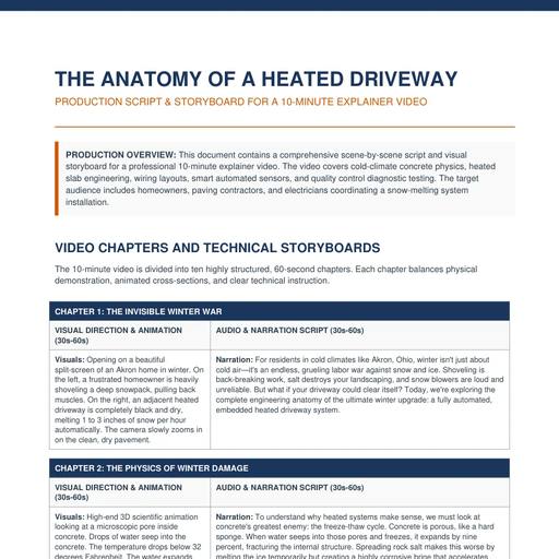
A full-coverage system on a 20 x 20 ft driveway draws 20 kW, which at 240 V is 83.3 running amps and 104.2 amps of continuous-load rating. On a 200-amp service the safe allowance for a single continuous heating load is 40% of the panel - 80 amps - so that layout fails the check before a single cable is laid. The same driveway heated as two 2-foot tire tracks draws 4 kW, 16.7 running amps and 20.8 continuous, fits one 30-amp GFEP breaker, and clears the 40% rule with room to spare. Coverage choice, not equipment brand, decides whether your Akron installation needs a service upgrade or a zoned controller.
Continuous load is the whole game
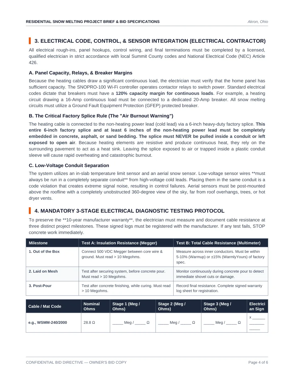
Heating cable is not a motor that starts and stops; it runs for hours. Under NEC Article 426 fixed outdoor de-icing and snow-melting equipment is treated as a continuous load, and the brief states the margin as 120% with a worked example: a circuit drawing a 16-amp continuous load connects to a dedicated 20-amp breaker. In practice the branch circuit is sized at 1.25 times the running amperage, then the installer settles on the next standard double-pole rating.
The short version
- A full-coverage system on a 20 x 20 ft driveway draws 20 kW, which at 240 V is 83.3 running amps and a 104.2 amp continuous-load rating that fails the check on a 200-amp panel.
- A residential service should allocate no more than 40% of the main panel rating to a single continuous heating load, giving 100 A, 200 A and 400 A panels allowances of 40, 80 and 160 amps.
- Residential branch circuits are limited to 40 amps of continuous load each, so 400 sq ft of full coverage arrives with three 40-amp breakers and the load must be split across zones rather than delivered in one feed.
- NEC Article 426 treats snow-melt cable as a continuous load with a 120% margin, so a 16-amp continuous load takes a dedicated 20-amp breaker and the branch is sized at 1.25 times the running amperage.
- Every snow-melting circuit must use a GFEP breaker with a 30 mA trip threshold, chosen to protect the buried cable and its jacket rather than people at the 5 mA level of a receptacle GFCI.
- The 6-inch factory hot-to-cold splice plus at least 6 inches of cold lead must be fully embedded, and the 10-year warranty requires a signed three-stage 500 VDC megohmmeter log above 10 megohms.
| Heated area | Draw at 50 W/sq ft | Running amps at 240 V | Continuous rating (x1.25) | 40 A branch circuits | Breaker per circuit |
|---|---|---|---|---|---|
| 80 sq ft (tire tracks) | 4 kW | 16.7 A | 20.8 A | 1 | 30 A |
| 100 sq ft | 5 kW | 20.8 A | 26.0 A | 1 | 30 A |
| 200 sq ft (walkway + approach) | 10 kW | 41.7 A | 52.1 A | 2 | 30 A |
| 400 sq ft (20 x 20 full) | 20 kW | 83.3 A | 104.2 A | 3 | 40 A |
| 600 sq ft (30 x 20 full) | 30 kW | 125.0 A | 156.3 A | 4 | 40 A |
Residential branch circuits for heating cable are limited to 40 amps of continuous load each, so the number of double-pole GFEP breakers is the continuous rating divided by 40, rounded up. That is why a 400 sq ft full-coverage installation arrives with three 40-amp breakers rather than one enormous one - and why the amperage has to be split across zones rather than delivered in a single feed.
The 40%-of-panel rule, applied to real services
A residential service should never allocate more than 40% of its main panel rating to a single continuous heating load. That gives a 100-amp panel 40 amps to work with, a 200-amp panel 80 amps, and a 400-amp panel 160 amps.
| Layout | Continuous load | 100 A panel (40 A allowance) | 200 A panel (80 A) | 400 A panel (160 A) |
|---|---|---|---|---|
| 80 sq ft tire tracks | 20.8 A | Fits | Fits | Fits |
| 100 sq ft | 26.0 A | Fits | Fits | Fits |
| 200 sq ft | 52.1 A | Fails | Fits | Fits |
| 400 sq ft full | 104.2 A | Fails | Fails | Fits |
| 600 sq ft full | 156.3 A | Fails | Fails | Fits, with 3.7 A to spare |
Three competent responses exist when the load exceeds the allowance, and the brief names them: reduce the heated square footage, switch to an optimised tire-track layout, or install sequentially zoned control panels that cycle heating areas so the peak draw never arrives all at once. A fourth - upgrading the service - is a real project with real cost and should be quoted explicitly rather than discovered at inspection.
GFEP, not GFCI, and the 30 mA figure
All snow-melting circuits must use a Ground Fault Equipment Protection breaker. GFEP equipment is specified at a 30 mA trip threshold, which is chosen to protect the equipment - the buried cable and its jacket - rather than to protect people at the 5 mA level a receptacle GFCI uses. A heating cable buried in wet concrete is exactly the failure case this device exists for, and the brief makes it mandatory rather than optional. The supply path in the specified design runs from the main service panel to a touchscreen or Wi-Fi controller with contactor relays, then to the double-pole GFEP breakers, then to a weatherproof junction box, and finally to the embedded cables.
The splice that burns out in minutes
Heating cable ends in a 6-inch factory hot-to-cold splice connecting the resistive element to the non-heating power lead. That entire 6-inch splice, plus at least 6 inches of the cold lead, must be fully embedded in concrete, asphalt or sand bedding. Resistive elements produce heat continuously and rely on the surrounding pavement as a heat sink; pulled inside a conduit or left in open air, the splice overheats and burns out. The script's phrasing is blunt: inside a conduit it will overheat and burn out in minutes. Separately, low-voltage sensor wiring must run in its own conduit - sharing a conduit with the high-voltage cold leads is a code violation that injects signal noise and causes control failures.
Testing, and the warranty you lose by skipping it
The 10-year manufacturer warranty is conditional on documented testing at three milestones. Test A is insulation resistance with a 500 VDC megohmmeter between the core conductor and the ground braid, which must read greater than 10 megohms. Test B is total cable resistance with a digital multimeter across the inner conductors, which must fall within 5 to 10% of nominal for Warmup systems or within plus or minus 15% for WarmlyYours. Both tests run out of the box, once the cable is laid on mesh but before the pour, and again post-pour while the concrete cures. The post-pour test is the one that matters most: a shovel nick during the pour is invisible, and the log is the only evidence that the circuit was intact before the slab went down.
| Milestone | Test A: insulation resistance | Test B: cable resistance | Purpose |
|---|---|---|---|
| Out of the box | 500 VDC Megger, core to ground braid, greater than 10 megohms | Within 5-10% (Warmup) or plus/minus 15% (WarmlyYours) of factory spec | Reject damaged stock before it is buried |
| Laid on mesh, pre-pour | Greater than 10 megohms after securing the system | Monitor during the pour to catch shovel cuts immediately | Catch installation damage while it is still fixable |
| Post-pour, curing | Greater than 10 megohms after finishing | Record final resistance and complete the signed warranty log | Registers the 10-year warranty |
Failure and maintenance truth table for the electrical side
Half of these rows are paperwork failures, and they all resolve the same way: the homeowner pays. The two physical ones are cheap to prevent and expensive to discover, because a splice that burns out inside the slab is a demolition job.
| Failure mode | Root cause | First symptom and threshold | Typical interval | Cost to fix | Prevention |
|---|---|---|---|---|---|
| Splice burnout inside the slab | The 6 in. factory hot-to-cold splice pulled into PVC conduit instead of being embedded | Dead circuit, with no melt on the next storm | Within minutes of first energising | New cable plus demolition and re-pour over the embedment, $4,000 to $12,000 | Splice plus at least 6 in. of cold lead fully embedded in concrete, asphalt or sand |
| Nuisance GFEP trips | Low-voltage sensor wire sharing a conduit with the cold leads, or moisture in the junction box | Breaker resets, then trips again mid-storm | First wet season | Re-routing the sensor conduit, plus a call-out every winter it is left | Separate conduit for sensor wiring and a weatherproof junction box |
| Panel fails the 40%-of-panel check | Continuous heating load above 40% of the main panel rating | Inspection rejection, or the main breaker trips when pre-heat fires | At inspection or first storm | Re-zoning or a service upgrade, quoted as a separate line | Watts / 240 V x 1.25, divided by 40 A per circuit, checked against 40% of the service |
| Warranty claim denied | No 500 VDC Megger log at the out-of-box, laid-on-mesh and post-pour milestones | The 10-year manufacturer warranty is refused | At the first fault | The entire embedded repair becomes the owner's project | Signed three-stage record: above 10 megohms, ohms within 5 to 10% (Warmup) or plus or minus 15% (WarmlyYours) |
| System runs when it should be off | Controller left on a manual timer instead of forecast sensing | kWh flat through rain, dry weeks and snowstorms alike | First season | Controller and sensor retrofit, plus the season overrun | Forecast-based controller with an aerial snow switch - the up-to-70% waste reduction in the script |
| Sensor never sees the storm | Aerial snow switch shadowed by a soffit, tree or hot dryer vent | Slab stays cold while snow accumulates | First storm | Sensor remount, labour only | Post-mount above the roofline with a 360-degree unobstructed sky view |
The Megger row decides who pays for every other one: the signed 500 VDC log is a condition of the 10-year warranty.
Akron and Summit County calibration
Two local numbers decide the panel question. The design load is the brief's 50 W/sq ft at 240 V run for the calculator's 6-hour storm plus 3-hour after-run across 10 storms at 16¢/kWh: $57.60 a season for 4 kW of tire tracks against $288 for 20 kW of full coverage. Service size then governs the fit - 100 A, 200 A and 400 A panels allow 40, 80 and 160 A of continuous load under the 40% limit, so a 20.8-amp tire-track circuit fits any of them. Permitting is the part owners underestimate: rough-ins, hookups and terminations are licensed work under Summit County code and NEC Article 426, priced by the notebook at $1,000 to $2,500.
Decision matrix: choose the electrical layout if...
- Choose one 30 A GFEP circuit if you are heating tire tracks at 20.8 continuous amps on a 100 A service or larger.
- Choose zoned 40 A GFEP breakers for 400 sq ft at 104.2 continuous amps, cycled rather than fed at once.
- Choose sequentially zoned control when the load exceeds 40% of the service but the coverage is fixed.
- Choose a different contractor if a bid proposes a receptacle GFCI instead of a GFEP breaker at 30 mA.
Electrical checklist for the bid
- State the heated area, calculated draw in kW, running amps and the 1.25 continuous rating in the quote.
- Show the breaker count and sizes: continuous rating divided by 40 A per branch circuit, rounded up, standard double-pole sizes.
- Show the 40%-of-panel check against the actual main service rating, and quote a service upgrade separately if required.
- Require GFEP double-pole breakers at 30 mA on every snow-melt circuit.
- Require the 6-inch factory splice and at least 6 inches of cold lead fully embedded, never in conduit.
- Require low-voltage sensor wire in a separate conduit, and the aerial sensor mounted above the roofline with a 360-degree sky view.
- Require signed three-stage test logs, with the ohm values recorded against nominal.
Sources
NEC Article 426 as the governing code for fixed outdoor electric de-icing and snow-melting equipment, the 120% breaker margin with the worked 16-amp-to-20-amp example, the mandatory GFEP protected breaker, the 6-inch factory hot-to-cold splice embedment rule with at least 6 inches of cold lead, the prohibition on pulling the splice into a conduit, the separate-conduit rule for low-voltage sensor wiring, the aerial sensor's 360-degree unobstructed sky view, and the three-stage testing protocol with the greater-than-10-megohm Megger threshold and the 5-10% / plus-minus-15% resistance tolerances are from the Residential Snow Melting Project Brief & Bid Specifications for Akron, Summit County, Ohio (v2.0) at /media/concrete-driveways/pdfs/heated-driveway-contractor-brief.pdf. The statement that a splice pulled inside a conduit overheats and burns out in minutes, and the 10-year warranty condition, come from the Anatomy of a Heated Driveway production script at /media/concrete-driveways/slides/. The 40-amp continuous limit per residential branch circuit, the 40%-of-panel allocation rule, the 30 mA GFEP trip level, the 125% continuous-load factor and the standard breaker sizes are the constants in the Concrete Paving & Driveway Calculator Development Prompts behind the sub-panel and GFEP sizer and the live heated-driveway calculator. All amp, kW, breaker-count and panel-fit figures in the tables are computed here from watts divided by 240 V, multiplied by 1.25, with no other assumptions.